Container Home Foundations: Pouring Concrete vs. Helical Piles
Deep technical comparison of foundation systems for serious container home builders
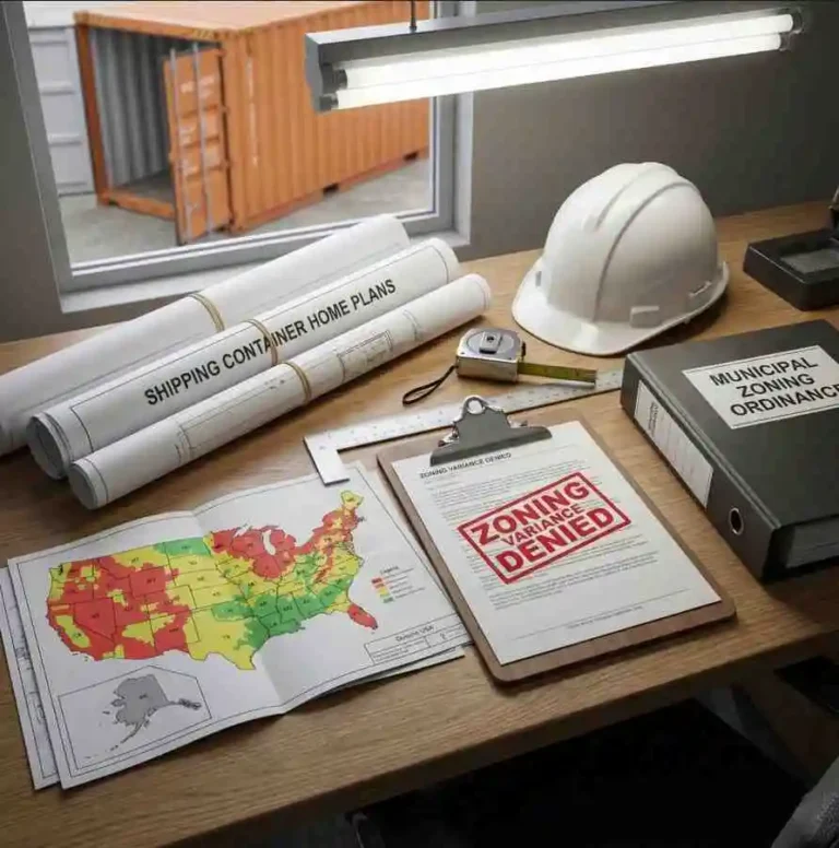
Selecting the right container home foundation determines structural integrity, longevity, and compliance with building codes for decades to come. Whether you choose poured concrete footings or helical pile systems, your foundation must transfer dead loads, live loads, and lateral forces from shipping container structures safely into bearing soil according to 2021 IRC/IBC standards.
Concrete foundations offer proven durability and maximum load-bearing capacity, while helical piles provide rapid installation and minimal site disturbance with comparable structural performance. Both foundation types meet code requirements when properly engineered, but the optimal choice depends on soil conditions, project timeline, budget constraints, and specific load requirements for your container home design.
This technical guide examines bearing capacity calculations, installation procedures, cost analysis, and code compliance for both foundation systems. You’ll understand load transfer mechanisms, soil interaction principles, and engineering considerations that Professional Engineers evaluate when stamping foundation plans for permit submission.
Understanding Container Home Foundation Requirements
Shipping container homes impose unique loading patterns that differ significantly from conventional residential construction. A standard 40-foot high-cube container weighs approximately 8,600 pounds empty, with corner castings concentrated at four points rather than distributed along continuous wall lines. When fully built out with framing, insulation, utilities, and interior finishes, total dead load can exceed 30,000 pounds for a single container module.
Load Distribution Fundamentals
The 2021 IRC establishes minimum bearing capacity requirements based on soil classification and structure type. Foundation systems must resist vertical loads from dead weight and live occupancy loads, while simultaneously resisting uplift forces from wind, lateral loads from seismic activity, and potential frost heave in cold climates. Container homes require foundations that accommodate point loads at corner castings while maintaining structural stability across the entire footprint.
According to Table R401.4.1 of the 2021 IRC, presumptive load-bearing values range from 1,500 psf for clay and sandy clay soils to 4,000 psf for gravel and sandy gravel. Your foundation design must ensure that actual bearing pressure remains below these values after accounting for safety factors. Professional Engineers calculate exact bearing pressures using the total structure weight divided by the effective bearing area of footings or pile caps.
Soil Considerations
Soil type fundamentally influences foundation selection. Cohesive soils like clay experience volume changes with moisture fluctuations, potentially causing differential settlement. Granular soils like sand and gravel provide stable bearing but may require deeper embedment for lateral resistance. Expansive soils require special design considerations to prevent foundation movement during wet-dry cycles.
The International Code Council publishes the IRC, which establishes soil classification requirements and mandates geotechnical investigations for sites with questionable soil conditions. Where soil bearing capacity is uncertain, IRC Section R401.4 requires that foundation design be based on a foundation investigation performed by a qualified geotechnical professional.
IRC/IBC Code Requirements for Container Foundations
Foundation design for container homes must comply with Chapter 4 of the 2021 IRC or Chapter 18 of the 2021 IBC depending on occupancy classification and jurisdiction requirements. These codes establish minimum footing dimensions, reinforcement specifications, frost depth requirements, and bearing capacity verification procedures that apply to all residential foundation systems including those supporting shipping container structures.
Minimum Footing Requirements
IRC Section R403.1 specifies that footings must be supported on undisturbed natural soils or engineered fill, extend below frost line depth, and provide adequate bearing area based on soil classification. The minimum width for concrete footings is 12 inches with a minimum thickness of 6 inches, though actual dimensions must be calculated based on imposed loads and allowable soil bearing pressure.
📖 View Full IRC Section R403.1 Text
IRC Section R403.1 – General:
All exterior walls shall be supported on continuous solid or fully grouted masonry or concrete footings, crushed stone footings, wood foundations, or other approved structural systems that shall be of sufficient design to accommodate all loads according to Section R301 and to transmit the resulting loads to the soil within the limitations as determined from the character of the soil. Footings shall be supported on undisturbed natural soils or engineered fill.
Source: 2021 International Residential Code
Table R403.1.1 provides prescriptive footing dimensions for light-frame construction based on soil bearing capacity and building loads. For a two-story structure on soil with 1,500 psf bearing capacity, minimum footing width is 19 inches. These prescriptive values serve as starting points, but container home point loads often require engineered footings that exceed minimum code dimensions.
Deep Foundation Standards
Helical piles fall under deep foundation provisions in IBC Section 1810. The code requires that allowable axial load for helical piles be determined as one-half of the ultimate capacity, establishing a safety factor of 2.0. Ultimate capacity is the lesser of base capacity plus shaft resistance, capacity from installation torque correlations, capacity from load tests, or ultimate shaft capacity.
📖 View IBC Section 1810.3.3.1.9 – Helical Piles
IBC Section 1810.3.3.1.9 – Helical piles:
The allowable axial design load, Pa, of helical piles shall be determined as follows: Pa = 0.5 Pu where Pu is the least value of: 1. Base capacity plus shaft resistance of the helical pile. The base capacity is equal to the sum of the areas of the helical bearing plates times the ultimate bearing capacity of the soil or rock comprising the bearing stratum. The shaft resistance is equal to the area of the shaft above the uppermost helical bearing plate times the ultimate skin resistance. 2. Ultimate capacity determined from well-documented correlations with installation torque. 3. Ultimate capacity determined from load tests where required. 4. Ultimate axial capacity of pile shaft. 5. Ultimate axial capacity of pile shaft couplings. 6. Sum of the ultimate axial capacity of helical bearing plates affixed to pile.
Source: 2021 International Building Code
Seismic Design Considerations
In Seismic Design Categories D0, D1, and D2, IRC Section R403.1.3 mandates additional reinforcement for concrete footings. Not fewer than one No. 4 horizontal bar must be installed within 12 inches of the top of stem walls, and one No. 4 horizontal bar located 3 to 4 inches from the bottom of footings. Vertical reinforcement is required at maximum 4-foot spacing with standard hooks extending to the bottom of footings.
| Foundation Type | Code Section | Key Requirement |
|---|---|---|
| Concrete Footings | IRC R403.1.1 | Minimum 12″ width, 6″ depth |
| Helical Piles | IBC 1810.3.3.1.9 | Safety factor 2.0 on ultimate capacity |
| Seismic Reinforcement | IRC R403.1.3 | No. 4 bars top and bottom (SDC D0-D2) |
| Frost Protection | IRC R403.1.4 | Below frost line per Figure R301.2(1) |
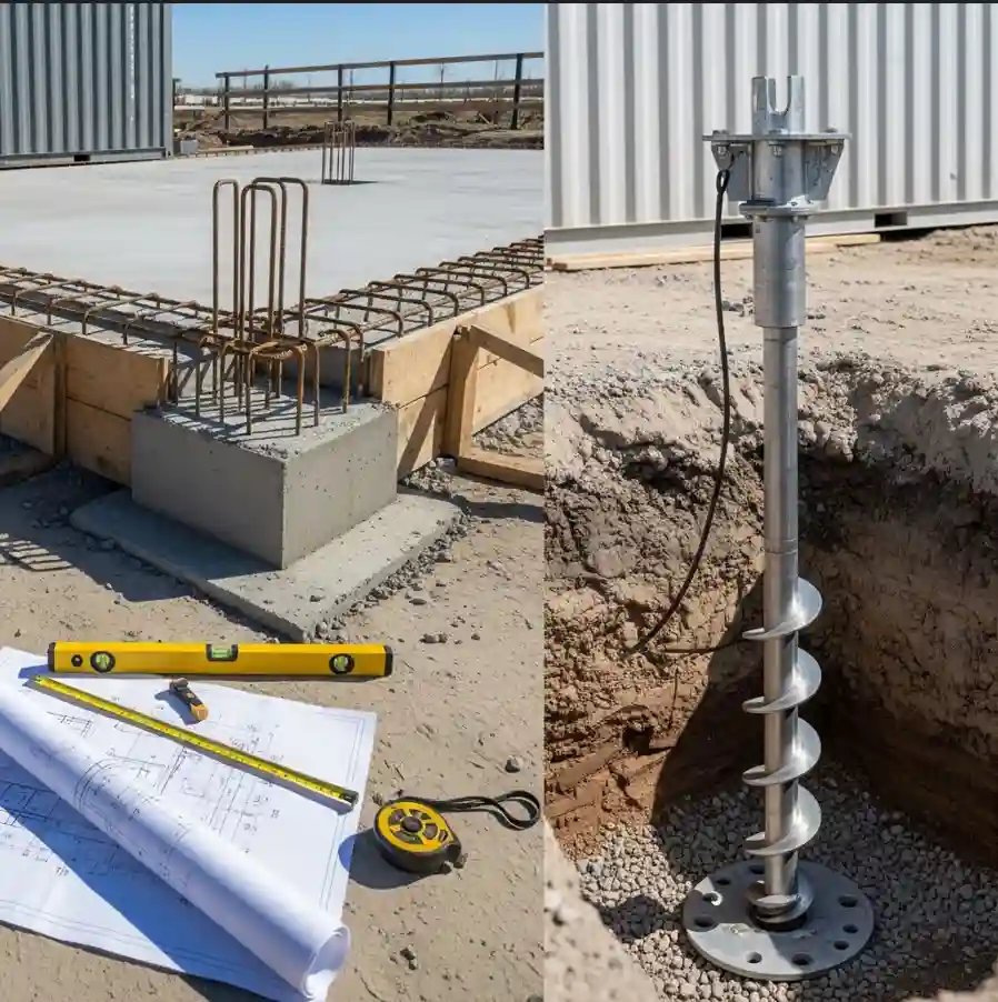
Poured Concrete Foundation Systems
Poured concrete foundations for container homes typically utilize one of three configurations: continuous strip footings with piers at corner points, isolated spread footings beneath each corner casting, or monolithic slab-on-grade with thickened edges at load points. Each system provides reliable load transfer when properly designed and constructed according to IRC specifications and engineered for site-specific conditions.
Strip Footing with Pier Configuration
Strip footings run continuously along container edges, providing uniform support and superior resistance to differential settlement. Concrete piers rise from the strip footing to meet container corner castings, elevating the structure above grade for drainage, ventilation, and utility access. This configuration works exceptionally well for multi-container assemblies where intermediate support is required between corner points.
IRC Table R403.1.1 specifies minimum footing dimensions, but container point loads often require wider footings calculated by dividing the corner load by allowable soil bearing pressure. For a 10,000-pound corner load on soil with 2,000 psf capacity, minimum footing area is 5 square feet. Adding safety factors and accounting for footing self-weight typically increases this to 6-8 square feet of bearing area per corner.
Isolated Spread Footings
Isolated spread footings place independent concrete pads directly beneath each container corner casting. This economical approach minimizes concrete volume and excavation work while concentrating foundation elements exactly where structural loads occur. Proper design requires tie beams or grade beams connecting isolated footings to resist lateral loads and prevent independent movement.
Reinforcement requirements for spread footings depend on footing dimensions and applied loads. IRC Section R403.1.3.5 requires steel reinforcement to have minimum yield strength of 40,000 psi with concrete cover of 3 inches where cast against earth. Typical spread footings for container corners use No. 4 rebar in a grid pattern with 12-16 inch spacing, though Professional Engineers determine exact reinforcement based on calculated bending moments.
📖 View IRC Section R402.2 – Concrete Requirements
IRC Section R402.2 – Concrete:
Concrete shall have a minimum specified compressive strength of f’c as shown in Table R402.2. Concrete subject to moderate or severe weathering shall be air entrained. The maximum weight of fly ash, other pozzolans, silica fume, slag or blended cements that is included in concrete mixtures for garage floor slabs and for exterior porches, carport slabs and steps exposed to the weather shall not exceed the percentages of the total weight of cementitious materials specified in Section R402.2.
Source: 2021 International Residential Code
Slab-on-Grade Foundations
Monolithic slab foundations integrate a 4-6 inch structural slab with thickened edge beams or turned-down footings at perimeter and load points. Container corners rest on embedded steel bearing plates or cast-in-place pilasters that transfer loads into the slab structure. This system excels in warm climates with shallow frost depths and provides finished floor surface in a single concrete placement.
Minimum concrete compressive strength for footings is 2,500 psi per IRC Table R402.2, though 3,000-3,500 psi is standard practice for improved durability and crack resistance. For additional guidance on residential building requirements and concrete performance standards, the U.S. Department of Energy provides resources on meeting energy code standards and foundation insulation requirements for container home projects.
Helical Pile Foundation Systems
Helical piles consist of steel shafts with welded helical bearing plates that are mechanically rotated into bearing strata, creating deep foundations without excavation or concrete curing time. Load capacity derives from bearing resistance of helical plates in competent soil layers combined with shaft friction along the embedded length. Installation torque correlates directly with load capacity, providing real-time verification during placement that concrete foundations cannot offer.
Load Transfer Mechanisms
As installation torque increases, helical plates compress soil beneath them, creating dense bearing zones. Multiple helical plates distribute loads across different soil strata, with plate spacing typically equal to three times the plate diameter to ensure independent bearing failure zones. The uppermost plate should be embedded at least five plate diameters below final grade to prevent surface soil influence on capacity.
IBC Section 1810.3.2.6 establishes allowable stresses for helical pile materials. Steel in compression is limited to 0.6 Fy (yield strength) for piles meeting enhanced verification criteria, or 0.35 Fy for standard installations. For Grade 50 steel commonly used in helical piles, this translates to allowable compressive stress of 30,000 psi for enhanced designs or 17,500 psi for standard applications.
Installation Process and Verification
Helical piles install using hydraulic drive heads mounted on compact equipment or hand-held units for limited-access sites. Torque monitoring during installation provides continuous capacity verification through established torque-to-capacity correlations. When installation torque reaches the value corresponding to required design capacity, the pile has achieved adequate embedment and bearing.
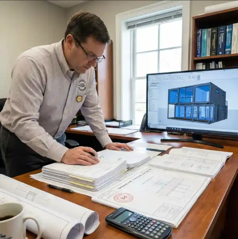
After purchasing comprehensive plans from PermitContainerhomes.com, you’ll work with a licensed PE who will review the detailed documentation, specify helical pile requirements based on your soil conditions, and provide stamped drawings required for permit submission. Your PE will determine pile diameter, helix configuration, embedment depth, and required installation torque values specific to your project site.
| System Component | Typical Specification | Cost Range |
|---|---|---|
| Helical Pile (8-12 ft depth) | 2.875″ shaft, 10″-14″ helixes | $150-$300 per pile |
| Installation Labor | Hydraulic installation equipment | $75-$150 per pile |
| New Pile Brackets | Steel attachment plates | $50-$100 per corner |
| Engineering/Stamping | PE review and calculations | $2,000-$5,000 total |
| Typical 40′ Container (4 piles) | Complete foundation system | $3,000-$5,500 installed |
Note: Costs vary significantly by location, soil conditions, access limitations, and market conditions. Installation in difficult soils or requiring deeper embedment increases material and labor costs. These are general estimates for comparison purposes.
Performance Characteristics
Helical piles achieve full rated capacity immediately upon installation, eliminating the 28-day curing period required for concrete foundations. This accelerated timeline proves particularly valuable for projects with tight construction schedules or weather constraints. Piles resist uplift forces through helical plate bearing against overlying soil, making them excellent for high-wind coastal applications or structures with significant roof overhangs.
📖 View IBC Table 1806.2 – Allowable Foundation Pressure
IBC Table 1806.2 – Allowable Foundation and Lateral Pressure:
CLASS OF MATERIALS – ALLOWABLE FOUNDATION PRESSURE (psf): 1. Crystalline bedrock: 12,000 psf | 2. Sedimentary and foliated rock: 4,000 psf | 3. Sandy gravel and gravel (GW and GP): 3,000 psf | 4. Sand, silty sand, clayey sand (SW, SP, SM, SC): 2,000 psf | 5. Clay, sandy clay, silty clay, silt (CL, ML, MH and CH): 1,500 psf. The allowable bearing pressures apply to foundations designed in accordance with strength design or allowable stress design procedures. An increase of one-third is permitted when using allowable stress design load combinations that include wind or seismic loads.
Source: 2021 International Building Code
Limitations and Considerations
Helical piles require competent bearing strata within economically feasible depths, typically 8-30 feet below grade. Rocky or extremely dense soils may prevent pile advancement or cause helical plate damage during installation. Loose granular soils with low bearing capacity require larger or multiple helical plates to develop adequate bearing area, potentially increasing costs compared to concrete alternatives.
Comparative Analysis: Performance and Cost
Selecting between poured concrete and helical pile foundations requires evaluating multiple performance dimensions including structural capacity, installation timeline, site impact, long-term durability, and total project costs. Each foundation system offers distinct advantages depending on site conditions, project constraints, and builder priorities for your container home construction.
Installation Timeline Comparison
Concrete foundations require excavation, formwork construction, rebar placement, concrete placement, and 28-day curing before container placement. Weather delays during any phase extend timelines significantly. A typical four-corner concrete foundation system requires 5-10 working days from excavation start to container-ready status, not including curing time.
Helical pile installations complete in 4-8 hours for a standard single-container foundation. Piles achieve full rated capacity immediately, allowing same-day container placement and construction continuation. This timeline advantage proves particularly valuable in regions with short construction seasons or projects requiring rapid enclosure before weather changes.
Structural Performance Factors
Properly engineered concrete foundations provide virtually unlimited bearing capacity constrained only by soil conditions and footing size. Large spread footings easily accommodate multi-story container stacks or heavily loaded structures. Concrete’s mass and rigidity provide excellent resistance to lateral loads and superior performance in high seismic zones when reinforced according to IRC Section R403.1.3.
Helical piles typically provide 20,000-50,000 pounds capacity per pile depending on shaft diameter, helix configuration, and bearing soil characteristics. This capacity range accommodates most residential container home applications including two-story structures. Pile groups can be designed for higher loads, though economic efficiency decreases compared to concrete footings for very heavy structures.
Site Condition Adaptability
Concrete foundations require stable excavations and adequate working space for formwork and concrete trucks. Sites with high water tables, unstable trench walls, or restricted access present challenges requiring dewatering, shoring, or specialized placement equipment. Expansive clay soils demand deeper footings or special foundation designs adding significant costs to concrete systems.
Helical piles excel in challenging site conditions including high water tables, limited access locations, and sites with variable soil layers. Compact installation equipment operates in spaces inaccessible to concrete trucks. Piles advance through weak surface soils to reach competent bearing strata below, eliminating concerns about seasonal soil moisture changes affecting foundation performance.
Total Cost Analysis
Material costs for concrete foundations vary by region but typically range $800-$1,500 per corner including excavation, formwork, concrete, reinforcement, and labor for basic spread footings or pier systems. Complex sites with difficult soils, deep frost lines, or access limitations increase costs substantially. Strip footing systems connecting multiple corners cost more due to increased concrete volume but provide superior structural integration.
Helical pile foundations typically cost $225-$400 per pile installed including materials, installation labor, and brackets. A standard 40-foot container requires four piles for $900-$1,600 total foundation cost. This represents 20-40% savings compared to concrete alternatives in many applications. Cost advantages increase significantly for difficult sites where helical installation avoids expensive excavation, shoring, or soil stabilization required for concrete foundations.
| Comparison Factor | Poured Concrete | Helical Piles |
|---|---|---|
| Installation Time | 5-10 days + 28-day cure | 4-8 hours, immediate use |
| Typical Capacity/Point | 10,000-50,000+ lbs | 20,000-50,000 lbs |
| Site Impact | Significant excavation | Minimal disturbance |
| Cost per Corner | $800-$1,500 | $225-$400 |
| Weather Sensitivity | High (freeze/rain delays) | Low (all-season install) |
| Quality Verification | Visual inspection only | Torque monitoring documentation |
Long-Term Durability Considerations
Concrete foundations properly designed and constructed provide century-scale service life with minimal maintenance. Adequate cover over reinforcement prevents corrosion, while proper concrete mix design resists freeze-thaw damage and chemical attack. Settlement risks exist if bearing soil compresses over time, though proper soil preparation and footing sizing mitigate this concern.
Galvanized helical piles resist corrosion for 50-100+ years in most soil conditions. Hot-dip galvanization provides zinc coating that sacrificially protects steel substrate from oxidation. In highly aggressive soil environments with low pH or high chloride content, enhanced coatings or increased safety factors address accelerated corrosion potential. Regular inspection intervals verify continued structural integrity, though in-ground conditions make inspection challenging compared to exposed concrete.
Professional Engineering and Installation
Both concrete and helical pile foundations require Professional Engineer involvement to ensure code compliance, proper design for site-specific conditions, and permit approval. The engineering process evaluates soil characteristics, structure loads, environmental factors, and local code requirements to produce stamped construction documents acceptable to your building department.
Essential Engineering Services
- Soil Analysis Review: Your PE evaluates geotechnical investigation data or conducts site assessment to determine bearing capacity, soil classification, and special conditions requiring design accommodation. Expansive soils, high water tables, or low bearing capacity trigger additional design requirements.
- Load Calculations: Engineers calculate dead loads from container structure, live loads from occupancy, roof loads from snow accumulation, and lateral loads from wind and seismic forces. These calculations determine required foundation capacity and sizing to meet IRC Section R301 load requirements.
- Foundation Design: Based on loads and soil conditions, your PE selects foundation type, determines footing dimensions or pile specifications, specifies reinforcement requirements, and details connections between foundation and container structure. Designs include safety factors per IBC Section 1810 for helical piles or IRC Section R403 for concrete footings.
- Construction Documents: Stamped drawings show foundation layout, dimensions, reinforcement details, material specifications, and installation requirements. These documents satisfy building department submittal requirements and guide contractor installation to ensure constructed foundation matches engineered design.
- Inspection Support: Professional Engineers may provide construction observation services, review contractor submittals, interpret plan requirements, and respond to field questions during foundation installation. This involvement ensures construction fidelity to design intent.
Critical Installation Requirements
Concrete foundation installation demands attention to excavation depth, bearing surface preparation, formwork accuracy, reinforcement placement per plans, concrete consolidation to eliminate voids, and proper curing procedures. IRC Section R403.1.3.5.3 requires 3-inch minimum cover for reinforcement cast against earth. Inspections typically occur at excavation completion, before concrete placement with reinforcement exposed, and at final completion.
Helical pile installation requires certified installers with calibrated torque monitoring equipment, proper pile handling to prevent damage, vertical alignment within tolerance, embedment to specified depth or torque achievement, and documented torque reports for each pile. Quality installation directly determines capacity achievement and long-term performance.
Key Takeaways for Foundation Selection
- Match Foundation to Site Conditions: Concrete footings excel on stable sites with good access, while helical piles solve problems presented by difficult soils, limited access, or challenging site conditions requiring minimal disturbance foundation solutions.
- Consider Total Project Timeline: Helical pile installation completes in hours versus weeks for concrete, potentially saving significant schedule time and associated costs for projects with tight timelines or weather constraints.
- Evaluate Life-Cycle Economics: Lower initial cost for helical piles may prove advantageous for temporary structures or projects with budget constraints, while concrete foundations provide maximum long-term value for permanent installations despite higher upfront investment.
- Prioritize Professional Engineering: Both foundation systems require PE involvement for code compliance and permit approval. Engineering costs of $2,000-$5,000 represent essential investment ensuring structural safety and regulatory compliance throughout your container home’s service life.
- Plan for Future Modifications: Concrete foundations more easily accommodate additions, structural changes, or increased loads through supplemental footings. Helical pile systems allow expansion by adding piles but require access for installation equipment.
With comprehensive planning documentation, Professional Engineer support, and understanding of your site requirements, you can confidently select the foundation system that optimally balances performance, cost, and construction considerations for your container home project.
Ready to Start Your Container Home Project?
Explore our collection of comprehensive container home plans designed to align with 2021 IRC and IBC building code standards. Each plan includes complete architectural drawings, structural details, foundation specifications, electrical layouts, plumbing systems, and beautiful 3D visualizations—everything your Professional Engineer needs for efficient review and foundation design.
Browse Complete Plan Collection →Need Plan Modification? If you find a plan you love but need to adjust it for your local climate or personal needs—such as modifying foundation details or adapting for specific site conditions—our team can help. We offer a professional plan modification service after purchase. Simply contact us with your modification needs, and we’ll provide a personalized quote.
⚖️ Professional Engineering & Plan Documentation Disclaimer
Important: Our plans are permit-ready but require review and stamping by a local licensed Professional Engineer (PE) in your jurisdiction. Final approval is subject to local building codes and regulations. We recommend consulting your local building department to verify all requirements.
Refund Policy: Due to the digital nature of our plans, all sales are final. Please review our Refund Policy for details.